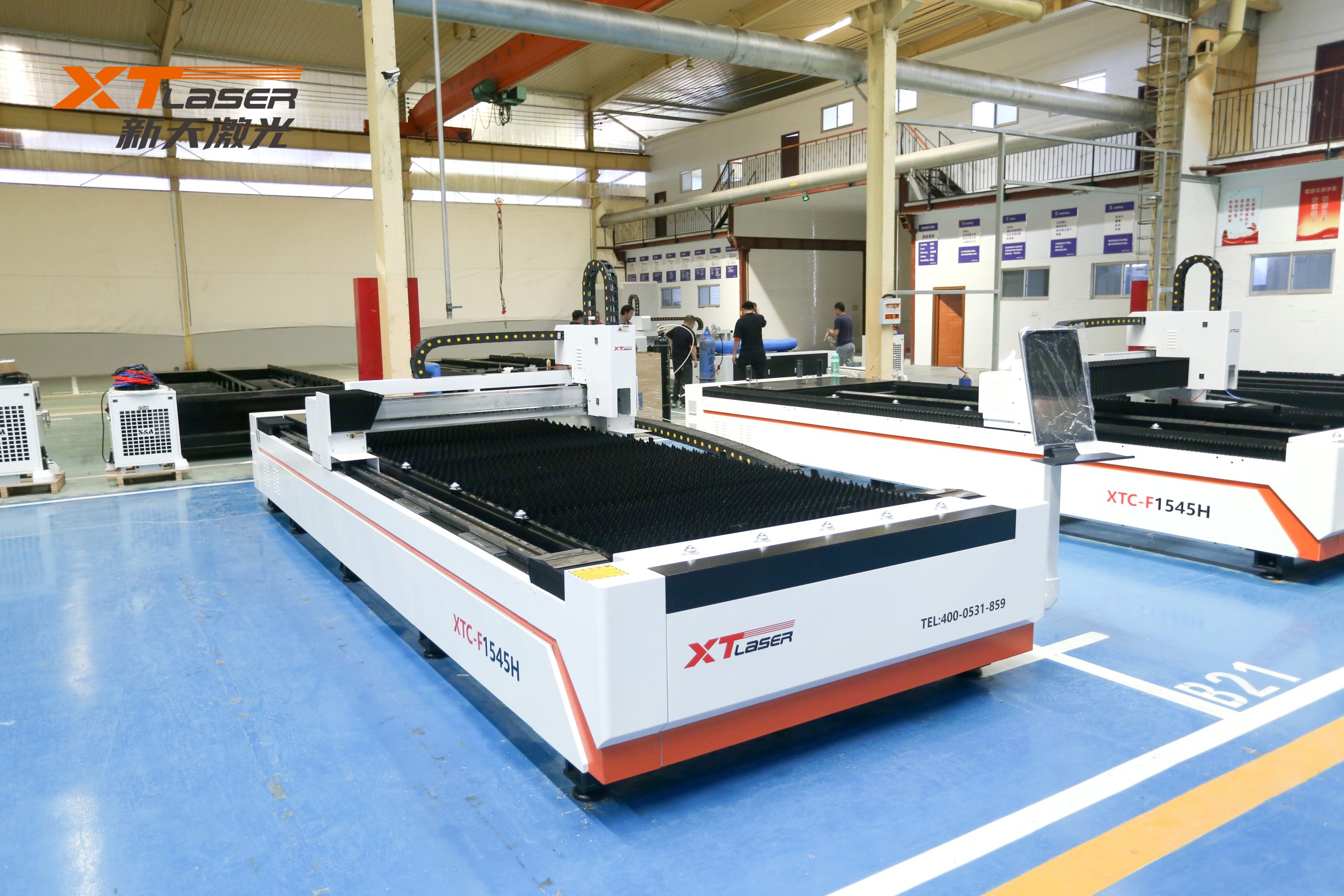
Acceptance steps for laser cutting machine
Attention to details when accepting laser cutting machines
After purchasing a laser cutting machine, it is necessary to inspect and accept equipment that meets the acceptance standards and specifications. So, what are the steps for us to inspect and accept a laser cutting machine? What issues should be noted? Let’s take a look together.

Technical documentation
Mainly the equipment installation diagram, electrical schematic diagram, electrical wiring diagram, mechanical structure diagram, user manual, certificate of conformity, packing list, list of vulnerable parts, and system software backup that are consistent with the purchased equipment (electronic version can be provided if necessary, or 2 paper documents if not possible).
List of main components of the transmission system (paired high-precision bearings, high-precision linear ball guide rails, high-precision reducers and gears, high-precision gear racks), models, prices, and related parameters; The brand, model, and price of the main components of the pneumatic system (pressure reducing valve, throttle valve, one-way valve, pressure switch, cylinder, solenoid valve, and electronic proportional valve);
Physical acceptance
Compare the packing list and confirm the quantity of equipment accessories and accompanying accessories;
Installation size and location requirements: The equipment installation drawing agreed upon by the buyer shall prevail.
Basic accuracy inspection of gantry laser cutting machine:
1) The straightness tool or method for the X-axis longitudinal guide rail: straightness measuring instrument or straightedge light gap method.
2) The flatness tool or method for the X-axis longitudinal guide rail: a level gauge.
Bed inspection accuracy:
1) The straightness tool or method for the X-axis longitudinal guide rail: straightness measuring instrument or straightedge light gap method.
2) Flatness tool or method for X-axis longitudinal guide rail: level gauge.
Functional Acceptance
The maximum travel of the X-axis is ≥ 7m, the maximum travel of the Y-axis is ≥ 2m, and the travel of the Z-axis is 100mm ≤ L ≥ 190mm; Measuring tools: tape measure, caliper.
When cutting a plate with a thickness of 8mm, the cutting speed is ≥ 1800mm; Tool: stopwatch
When the thickness of perforated Q345 plate is 8m, ≤ 3s; Tool: stopwatch
Maximum cutting thickness ≤ 20m; Method: Experiment with 20mm thick plate
Marking width ≥ 2.5mm, depth ≥ 0.5mm, speed ≥ 10000mm/min (marking 25cm in length); Tools: Vernier scale, stopwatch
Method for detecting the effectiveness of overtravel protection device: Will the device stop when it reaches its maximum stroke. Safety monitoring method: Touch the safety photoelectric switch to stop the equipment;
Design a workpiece by a process engineer and measure the machining accuracy after processing; Tools: Vernier scale IV. Fill in the acceptance report, asset requisition form, enter it into the ERP system, and archive all documents and data;
Acceptance completed


